You have found www.hamrx8.com
Copyright.... Website created & maintained by GHQP

July 15, 2011
Lithophane Back lighting System
COMPLETED
The following are images and some brief descriptions covering the machining and assembly of my lithophane backlighting system.
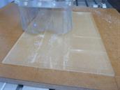
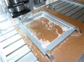
CNC machining the light diffuser.
For this I use 3mm thick clear acrylic sheet.
The cutting pattern is V grove parallel stripes, they are spaced 1.5mm.
The cutting tool I used was a 2Linc.com, Conical Engraving Tool, 0.1875" Dia, 60 Deg, 0.10" Tip For Soft material.
I set the cut depth to 0.15mm
The process took about 60 minutes to complete as I did it in 2 passes per grove.
I found that this produced very clean V groves without any residue or burring.
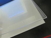
The first part of the assembly is to place a piece of white High Gloss Presentation Film as a backing on the opposite side to the grooved surface. This enhances the reflected light back to V grooved side. I used some thin pieces of double sided tape to attach it at each corner. This tape is the sort artists would use as it is clear less than paper thin.
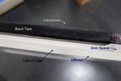
For this next part I used two 3mm thick off cuts left over from routing the outside profile of the diffuser as spacers between the diffuser and the lithophane. I used the thin clear double sided tape along the edges to secure the spacers and hold them in place.
Now this is quite significant. To stop light spillage from the LED directly onto the lithophane sheet, along the edge that is lit I blackend the edge of the lithophane sheet with a black permanent marker. I also use black electrical tape wrapped under by about 3mm and along the edge, as the photograph opposite shows.
Doing this significantly reduced and softened the high edge glare at the top and bottom where the LED strips are located.
Doing this significantly reduced and softened the high edge glare at the top and bottom where the LED strips are located.
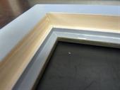
These shots show how I modified the frame to take the LED strips. As I was doing a few additional frames for use in the future I machined all four sides to accommodate the frame being used for portrait or landscape. I use the CNC router, for the first one I did by hand but then I created G-Code to do the rest under CNC control. The depth "Z" axis is calculated so that the bottom of the LED strip sits on the bottom ledge so as to position the centre of the LED Diode at the centre of the Difuser edge (I hope that is clear).
These final photos show the positioning of the LED strips (there is a strip at each end of the frame). Then with the assembled lithophane/diffuser assembly placed into the frame. I cut a piece of 3mm thick MDF to fit, and glued the original back with its stand that came with the frame to the MDF. Then finally I used black masking tape to hold the back in place. It just happened to work out, that with all this in place and due to the overall thickness of the frame I used, the back surfaces of the MDF and the frame matched up exactly. I used tape to hold it all together so that in the future if an LED strip needs replacing it won't be a problem to get apart.
