
You have found www.hamrx8.com
Copyright.... Website created & maintained by GHQP


Page Updated November 20, 2011
ACRYLIC WALL CLOCK
FINISHED
These images replace the previous ones I posted nearly a month ago.
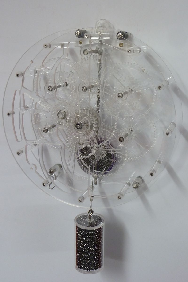
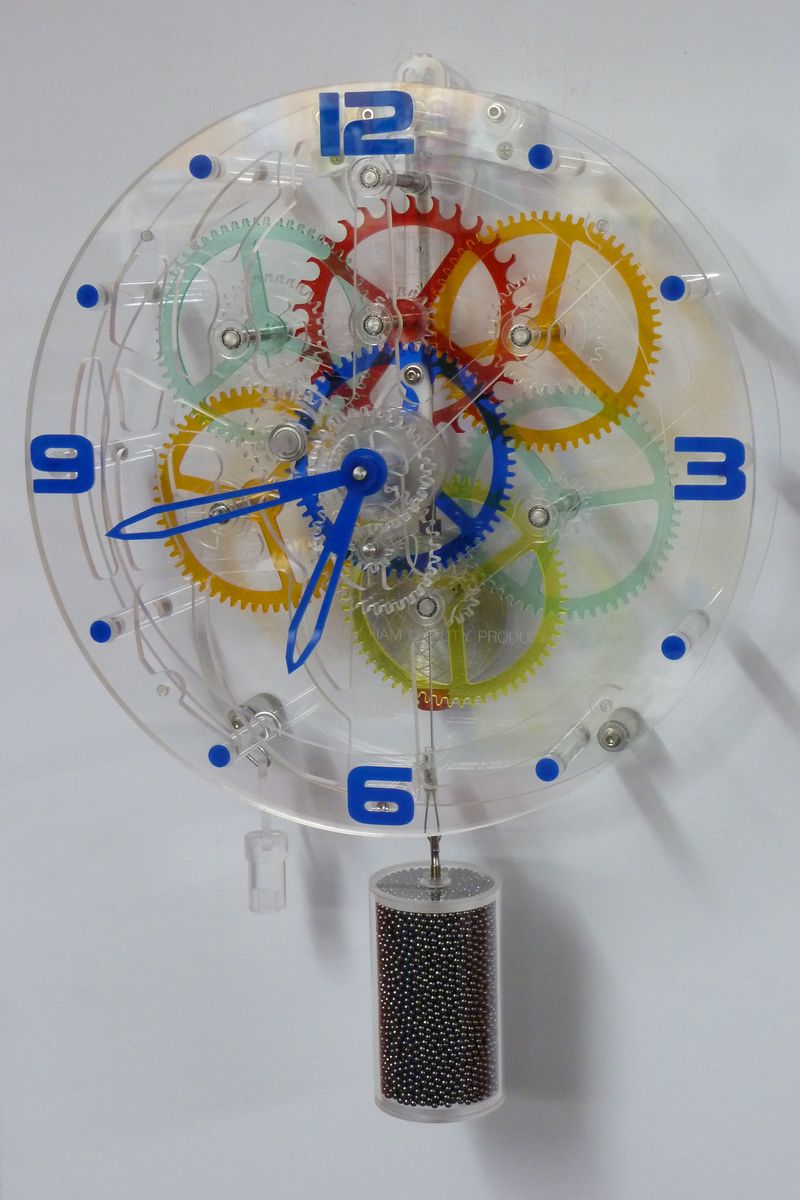
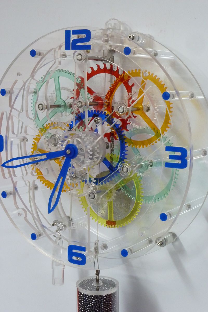
It is now complete and I have made two versions, one with mostly all clear Acrylic and the second with some coloured Acrylic gears. This page is mostly be a photographic collection rather than a lot of text explanation. The majority of machining was done on my CNC Router with a few parts needing to me made on the Lathe. Where appropriate I have placed a comment on the image that you will see when you click to display it.
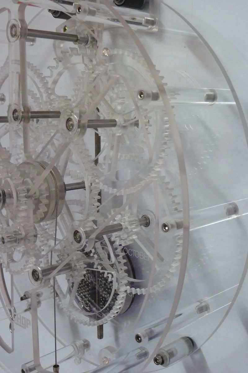
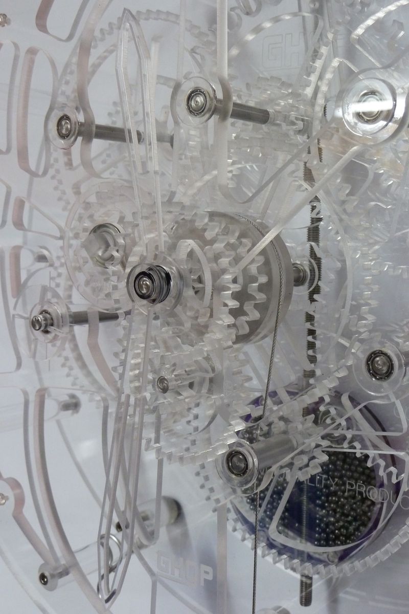
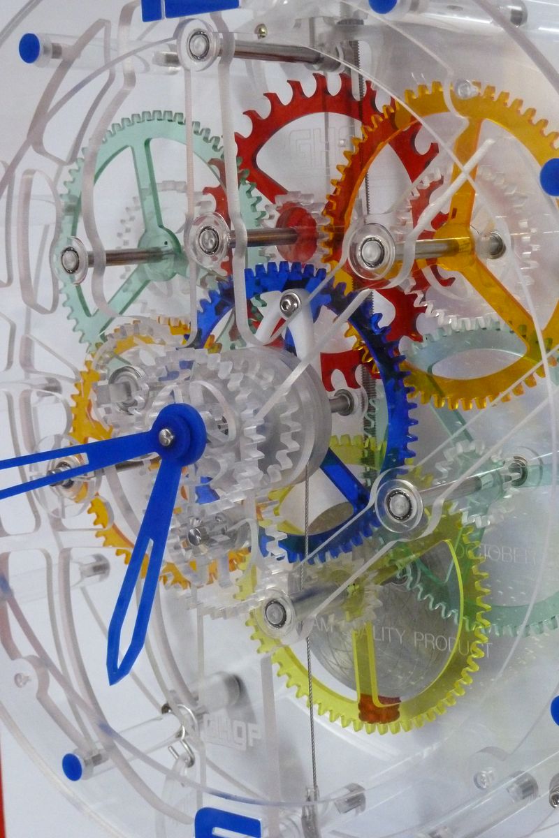
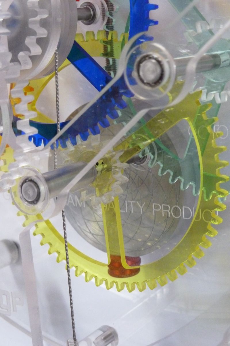
First a point of explanation, the original design for this clock was for it to be made from wood, the plans I purchased from Brian Law http://www.woodenclocks.co.uk/clock9.html These drawings and DXF files allowed me to create the CNC Router G-Code to machine many of the parts, most importantly the gear set. However I did make quite a few modifications, the first being the change from wood to Acrylic, The other significant change was to use small 6mm ID ball bearing races at each end of the shafts, with the shafts now being 6mm stainless steel rod.
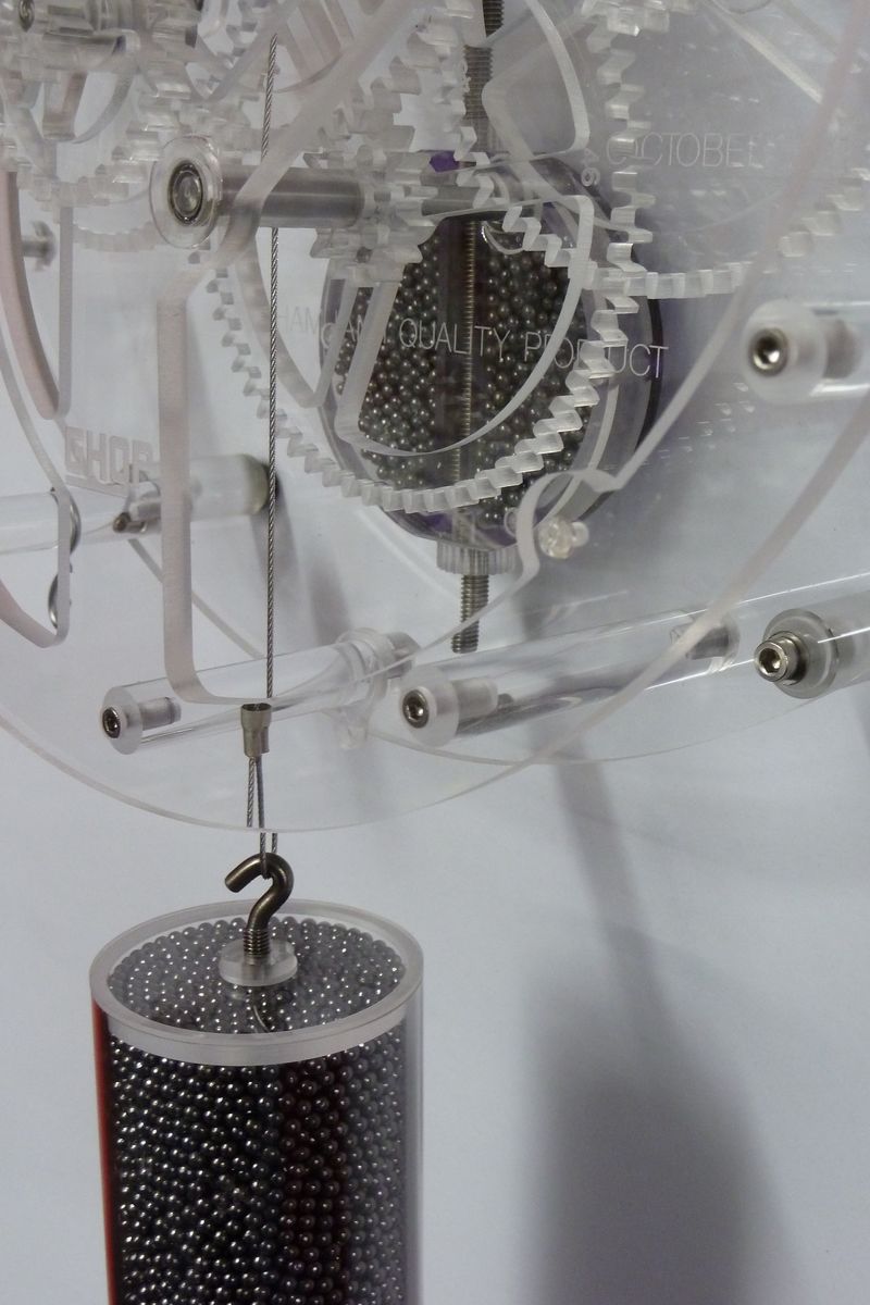
The biggest problem I had was the selection of material for the Pawl and Ratchet, I went from Acrylic to Aluminium and finally settled on Acetal (Delryn). I also changed the Drum design, I wanted to use Stainless Steel flexible cable for the Weight Rope. The Stainless Steel cable is only 1mm diameter so it meant that the Drum only need a single 1.2mm or so slot so the each layer of the cable lay directly on top of the previous one. (With a wide slot the cable digs in between rows and jams.) Slightly increasing the diameter of the Drum and the cable being only 1mm diameter gave me plenty of length the hang the clock more than 1.8 Meters high (from the centre shaft) on the wall, well above my eye level. One other point relating back to Brian Law's original wooden version, I discarded the case and made mine completely open, to do this I used 12 Acrylic spacers to separate and secure the Back and Front Boards. As for the Weight and Pendulum Bob I first used a big chunk of Aluminium for the weight and Brass for the Pendulum Bob. This didn't really go with the look and concept of using Acrylic. So I came up with designs that used Acrylic filled with Lead Shot, you will see these in the photographs below. There were various other design changes from the original Brian Law wooden version that had to be made to work with the fact I was using different materials and adding my own flair. Oh and one final point, if you look at Brian Law's design compared to mine you will notice two extra large gears. These have no actual function within the clock mechanism, they are simply there to make the clock more aesthetically symmetrical. After all I did not make this clock to be a technically accurate time piece, I think of it more as a moving piece of art that just so happens to also, when adjusted, keep pretty good time. Hung at about 1.8 Meters high it needs winding about every 11 - 12 hours. One final idea I am yet to make is to do away with the winding key and replace this with an extra gear and looped length of chain that can be pulled down to rotate the winding gear.. This is just an idea but I haven't been able to find a suitable chain so this hasn't been done and may never eventuate.
I started this project about 10 weeks ago and I admit there were quite a few frustrating times and lots of wasted Acrylic, without CNC I would have given up two weeks into it. However perseverance paid off with a huge feeling of personal satisfaction when it started to tick for the first time and to get up in the morning to find it still ticking. From that point I was enthused to refine all the finer design points to where it is today.
Now I am about to make a few more.
A big thank you to Brian Law for the inspiration and especially the dxf files of his original design as without it this clock would not exist.
I hope you find this an interesting project that you might have a go at yourself.
It is now complete and I have made two versions, one with mostly all clear Acrylic and the second with some coloured Acrylic gears. This page is mostly be a photographic collection rather than a lot of text explanation. The majority of machining was done on my CNC Router with a few parts needing to me made on the Lathe. Where appropriate I have placed a comment on the image that you will see when you click to display it.
First a point of explanation, the original design for this clock was for it to be made from wood, the plans I purchased from Brian Law http://www.woodenclocks.co.uk/clock9.html These drawings and DXF files allowed me to create the CNC Router G-Code to machine many of the parts, most importantly the gear set. However I did make quite a few modifications, the first being the change from wood to Acrylic, The other significant change was to use small 6mm ID ball bearing races at each end of the shafts, with the shafts now being 6mm stainless steel rod.
The biggest problem I had was the selection of material for the Pawl and Ratchet, I went from Acrylic to Aluminium and finally settled on Acetal (Delryn). I also changed the Drum design, I wanted to use Stainless Steel flexible cable for the Weight Rope. The Stainless Steel cable is only 1mm diameter so it meant that the Drum only need a single 1.2mm or so slot so the each layer of the cable lay directly on top of the previous one. (With a wide slot the cable digs in between rows and jams.) Slightly increasing the diameter of the Drum and the cable being only 1mm diameter gave me plenty of length the hang the clock more than 1.8 Meters high (from the centre shaft) on the wall, well above my eye level. One other point relating back to Brian Law's original wooden version, I discarded the case and made mine completely open, to do this I used 12 Acrylic spacers to separate and secure the Back and Front Boards. As for the Weight and Pendulum Bob I first used a big chunk of Aluminium for the weight and Brass for the Pendulum Bob. This didn't really go with the look and concept of using Acrylic. So I came up with designs that used Acrylic filled with Lead Shot, you will see these in the photographs below. There were various other design changes from the original Brian Law wooden version that had to be made to work with the fact I was using different materials and adding my own flair. Oh and one final point, if you look at Brian Law's design compared to mine you will notice two extra large gears. These have no actual function within the clock mechanism, they are simply there to make the clock more aesthetically symmetrical. After all I did not make this clock to be a technically accurate time piece, I think of it more as a moving piece of art that just so happens to also, when adjusted, keep pretty good time. Hung at about 1.8 Meters high it needs winding about every 11 - 12 hours. One final idea I am yet to make is to do away with the winding key and replace this with an extra gear and looped length of chain that can be pulled down to rotate the winding gear.. This is just an idea but I haven't been able to find a suitable chain so this hasn't been done and may never eventuate.
I started this project about 10 weeks ago and I admit there were quite a few frustrating times and lots of wasted Acrylic, without CNC I would have given up two weeks into it. However perseverance paid off with a huge feeling of personal satisfaction when it started to tick for the first time and to get up in the morning to find it still ticking. From that point I was enthused to refine all the finer design points to where it is today.
Now I am about to make a few more.
A big thank you to Brian Law for the inspiration and especially the dxf files of his original design as without it this clock would not exist.
I hope you find this an interesting project that you might have a go at yourself.


|

|

|

|

|

|

|

|

|

|

|

|

|

|

|

|

|

|

|

|

|

|
")
|

|

|

|

|

|

|

|

|
|
|
|
|

|
|
|
|
|

Click to see a video.