You have found www.hamrx8.com
Copyright... Website created & maintained by GHQP
Fitting an A2Z Antibacklash Leadscrew and Nut to my Sherline CNC Mill
Download Dimensioned Drawings.
The zip file Includes my original rough sketches.
The zip file Includes my original rough sketches.
Making the first prototype antibacklash nut mount
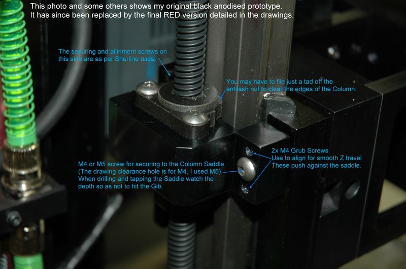
Refer to the last image for important information.
Refer to the last image for important information.
This is the second final version of the antibacklash nut mount. (3rd Jan. Updated 3 images)
This is the mount for the Z axis stepper or servo motor.
It is required to allign the screw with the antibacklash nut.
It is required to allign the screw with the antibacklash nut.
An overall view of my Sherline with all its attachments and modifications.
After assemble, to align the screw for smooth travel first have the cap screws for the motor mount just loose allowing it to find its natural location. Adjust all the antibacklash mount grub screws until they are just touching their bottom location. Every adjustment should feel as if they are in their natural position, (use your instinct). Once the 4 grub screws feel OK tighten their locking cap screws along with the motor mount screws. Now wind the Z axis saddle down by hand to see how it feels. You may have to make some other minor adjustments of the grub screws etc. but this process should not be too difficult. Remember you will have to re-set the Motor Tuning parameters for the Z Axis in MACH 3 to match the new lead screw pitch.
This modification to my Sherline CNC Mill was born out of the fact that A2Z who provide a great antibacklash system for the X and Y axis do not however have available a simple adapter to use this same leadscrew and antibacklash nut for the Z axis. The images on this page should provide most of the information you will need to duplicate my adaptation. Also at the bottom of this page here is a download link for my original sketches and dimensioned drawings. I tried to make everything as accurate as possible and be assured this works on my Sherline Mill flawlessly. However I can take no responsibility for the outcome for those of you who might replicate this system. My adapter designs are only for personal use and any commercialisation or re-publishing of it must have my approval first. I am open to any comments or suggestions for improvement.
January 26, 2011
Note: In relation to the Motor mount spacer, the dimensions for positioning the slots used to secure the spacer to the Sherline Z Column. You may find that if creating a CAD drawing the measurements will not exactly be as per my drawing. This is because I machined this part entirely by hand using my lathe and big Mill, then I took all these measurements manually from the finished part. It is all so close that it doesn't really matter, however the important dimension is the spacing between the slots. I show this as 20.77mm but in fact to be absolutely accurate in that the Sherline is made to imperial measurements the spacing is 13/16" that translates to 20.6375mm. Eyither way it will all fit and work fine as there is enough movement in the slots to compensate.
COMPLETED

